Beveling text with Geometry Nodes
· By Richard
Two years ago, I did a tutorial on how to make (nicer) text with Geometry Nodes.
A lot of people thought it was useful, but I also got a lot of requests to take it a step further: Bevel the text!
So that's what I'm sharing today: beveling text in Geometry Nodes.
The workflow looks like this:
- Turn a text string into curves
- Turn the curves into a flat mesh
- Extrude the mesh to make it 3D
- Bevel the edges with a single layer
- Bonus: Bevel with many layers for rounded bevels
And, we do everything in Geometry Nodes (no other modifiers).
This means we have to go deep, so strap in.
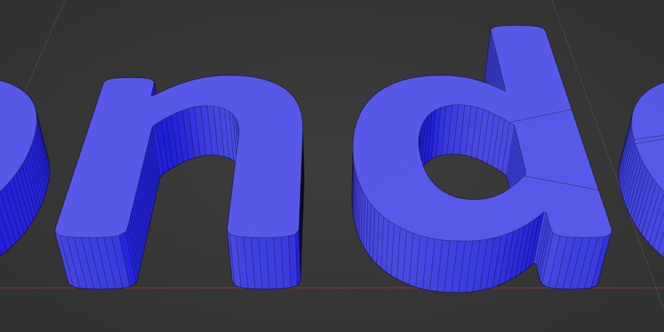
Starting where we left off
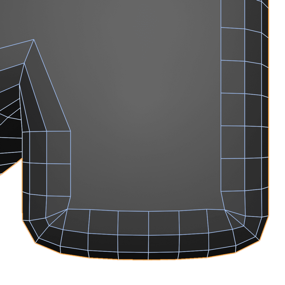
In the old tutorial, we covered steps 1-3 to end up with 3D text:
Here is the screencast again in case you want to see how we got to that point:
We also have a written version of it, so I won't spend too much time on how we got to this stage.
Beveling from first principles
Instead I'd like to dive straight into beveling.
This might sound a bit overwhelming to build from scratch with nodes. But once we break it down it's not too bad.
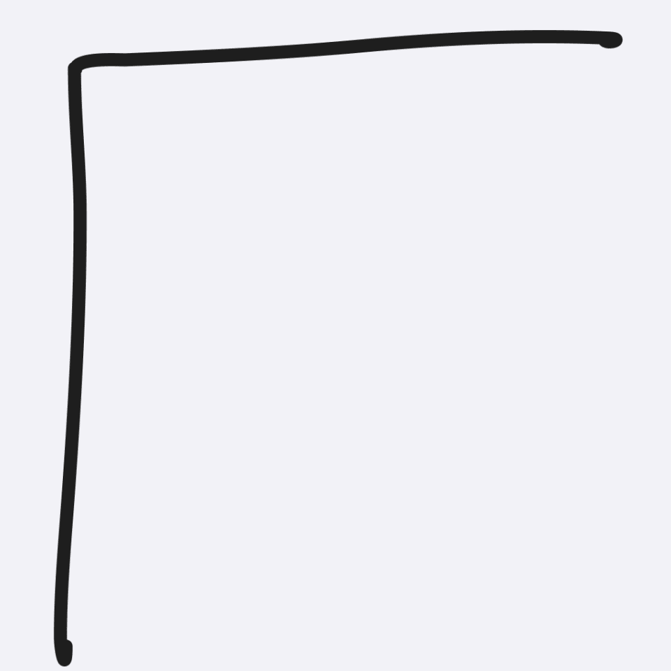
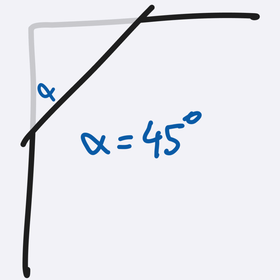
Let's look at the most simple type of bevel: Cutting the edges with a 45 degree angle.
If we do this on the default cube, so a 90 degree corner, this is what the side profile would look like:
And if we're starting from a flat mesh that we extrude to turn it into 3D, adding a bevel is pretty much adding a 2nd layer.
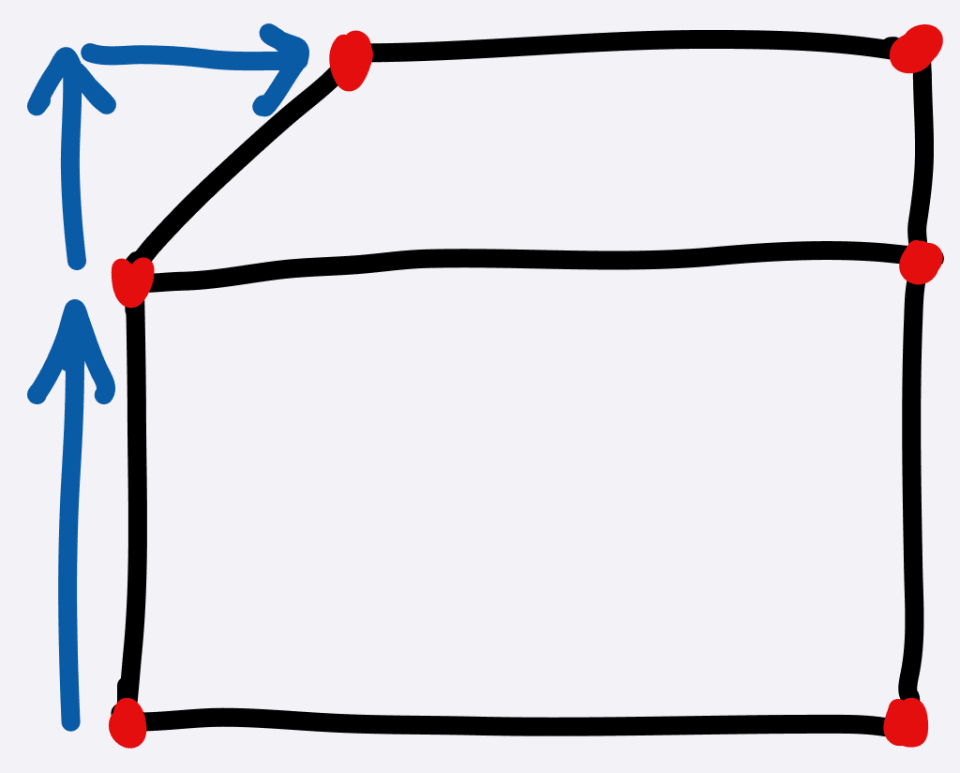
That second extrude layer is a bit special. Instead of only moving up, it also "shrinks" to get that 45 degree angle.
So our first challenge is figuring that shrinking out.
Shrinking the text
To shrink the text, we can use something very useful: The normals of the text curves!
This is how curves in Blender work:
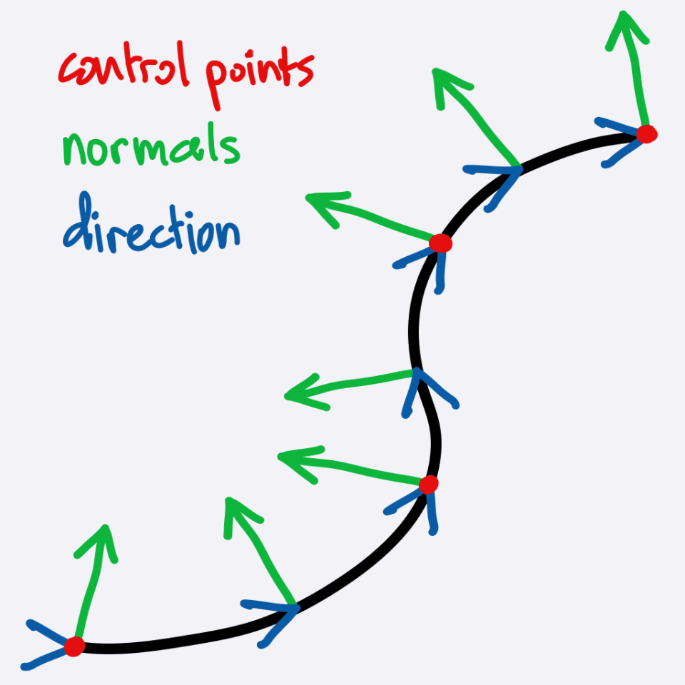
Curves have control points, a direction, and normals.
We can use the direction of the curve normals to shrink the text
The challenge is: How do we get these normal directions of the curve, while working with a mesh?
Capturing the curve normals
We have to pull the curve normals out and use them while extruding our mesh.
We will rely on the fact that our text curves have the same amount of points as the flat mesh we convert it into. (this is not always the case, in the screencast I explain more)
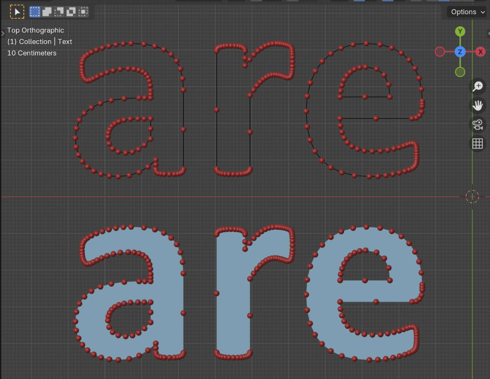
On top of that, we also rely on the fact that the order of these points doesn't change. In other words: The index of each point on the curve aligns with the index of each vertex in the mesh.
So while working in the context of the mesh, we can take the mesh vertex index and use it to sample the curve. Because the indices match, we will sample the right point on the curve.
So with index sampling, we can capture those curve normals!
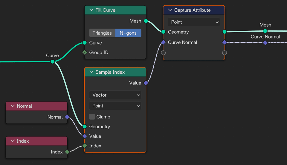
So we first sample the index, then capture the attribute in the mesh context.
If we now extrude the mesh, the captured curve normals are available in every extruded layer!
So to create beveled text, we first extrude straight up. Then we extrude up again a certain amount (the bevel distance), and we move that same amount along the curve normal.
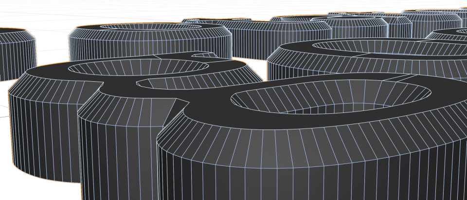
That gives us a simple beveled edge:
If you want to see this done live, check the screencast:
Multi layered beveling
What if we want to go beyond a simple 45 degree bevel? Let's say, a rounded bevel?
The only way to create a shape that looks round using a mesh, is using many steps / segments
So instead of a single extrude operation, we're going to have to figure out a way to repeat this multiple times.
Ideally we could enter an arbitrary number, and control the amount of repetitions.
We're lucky because there is a new concept in Geometry Nodes called a "Repeat Zone". It pretty much does what the name suggests: It is a zone where you can put stuff and repeat it as many times as you like.
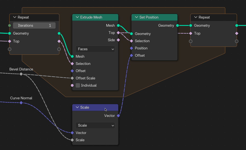
So we should place our final extrude operation into the repeat zone:
Now we can increase the number of iterations, and we get multiple layers of beveling :)
But it's still a 45 degree bevel.
To change the shape and make it rounded, we need some trigonometry.
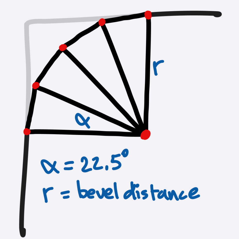
We could view the rounded bevel from the side, and then it's pretty much a quarter of a circle.
The bevel distance is the radius.
And the most straightforward way to subdivide it is by dividing it into parts with equal angles.
A quarter of a circle is 90 degrees. If we want a 4 layer bevel, we should use segments of 90/4 = 22.5 degrees each.
Now we calculate how high every extrusion should be, and how much it should shrink along the curve normal.
We have the radius, and the angle, so this is a matter of sine and cosine:
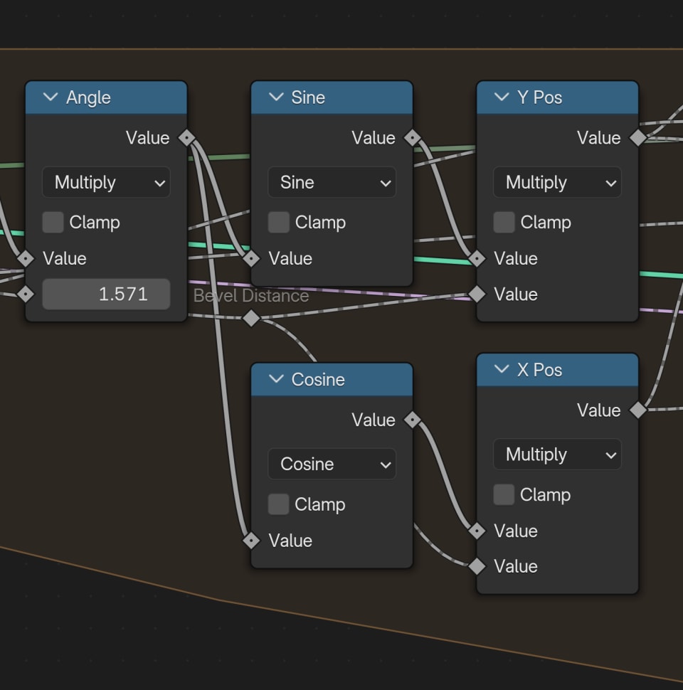
It's more tricky than this, because with sine and cosine we get the total amount to move up and in.
But what we need instead is the relative amount (compared to the last extrusion layer). So we plug in the nodes in a way where we remember the last X and Y position for the next step.
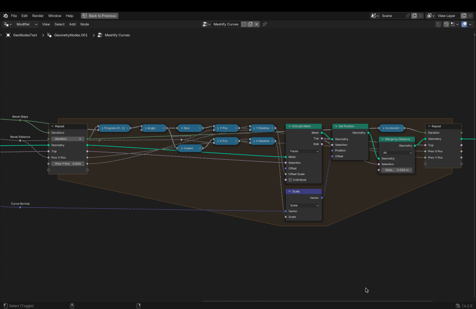
This is the final repeat zone setup:
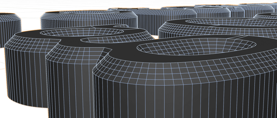
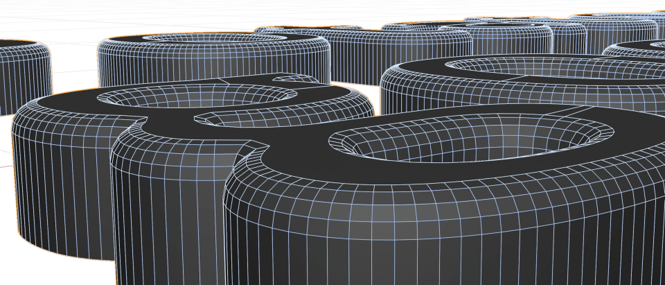
And that gives us a nice rounded bevel:
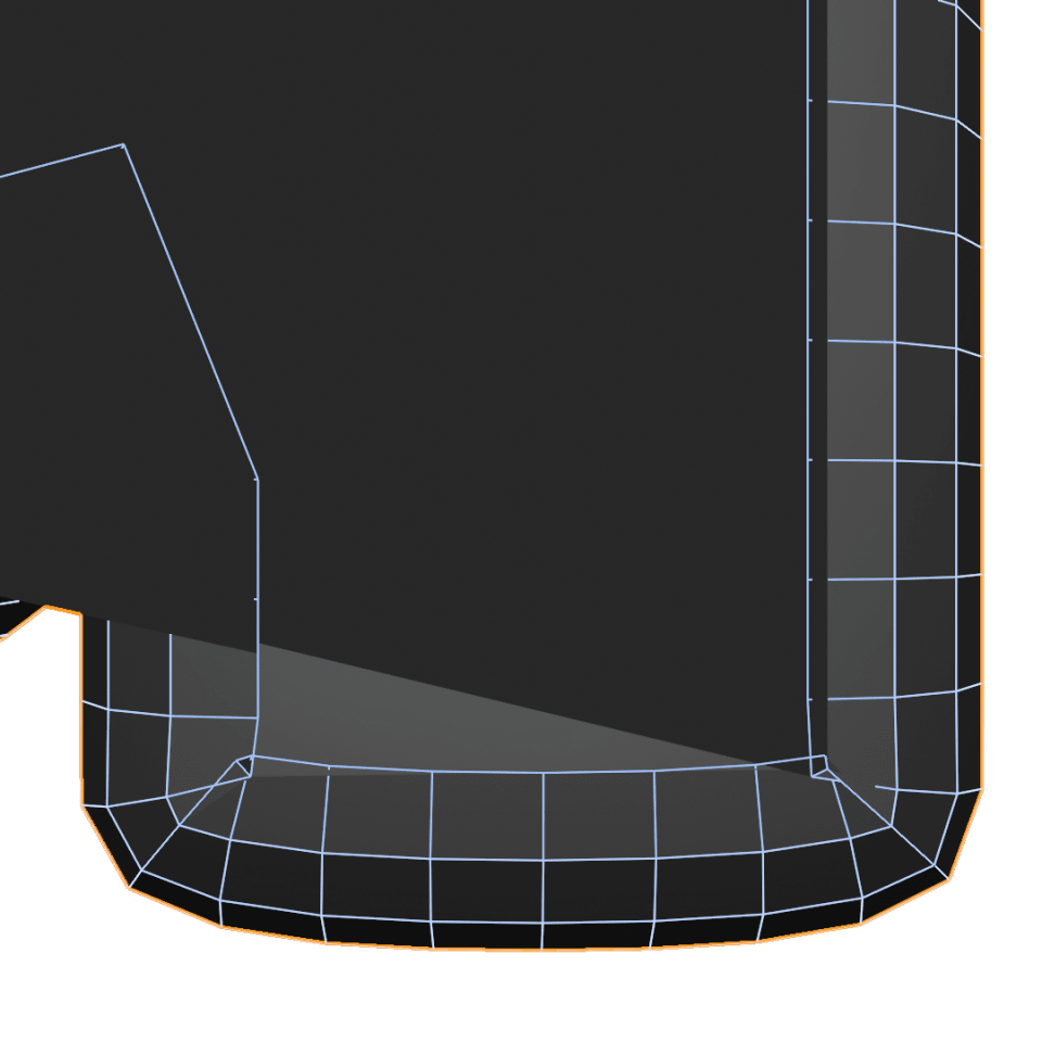
Another good improvement to add, to make the bevel more robust, is a Merge by Distance node.
This node can fix some issues when vertices get too close together. At a certain threshold distance, it will merge the vertices that are almost colliding.
If you want to see me do a walkthrough of the full setup, check the screencast here:
Final thoughts
I hope this was an interesting approach of using Geometry Nodes. In the future there might be a dedicated bevel node, that can do all this in 3 seconds.
But even if that happens, it's still useful to know how to think about this approach and set it up with basic nodes.
You can download the final resulting .blend file, as well as the intermediate .blend files here:
If you get a chance to play with this, let me know how it goes!